Module - 1 Scaling Networks
- Created: 2026-08-15
- Updated: 2026-08-28
- Tags:
#Network#CCNA#LAN#VLAN - Author: Duke Hsu
Chapter 1: LAN Design
Learning Objectives
- Design a LAN that can scale as users, devices, and applications increase.
- Improve availability by using redundancy and limiting failure domains.
- Select switches and routers according to their role and hardware capacity.
- Configure, verify, save, and erase basic Cisco IOS settings.
1.1 Campus Wired LAN Designs
1.1.1 Scaling a Network
A business network may begin with only a few users and devices, but it must be able to grow without requiring a complete redesign. A scalable network should:
- Support critical applications.
- Carry converged data, voice, and video traffic.
- Support changing business requirements.
- Provide centralized administration and monitoring.
- Maintain acceptable performance as traffic increases.
- Allow new users, access switches, and services to be added predictably.
1.1.2 Hierarchical LAN Design
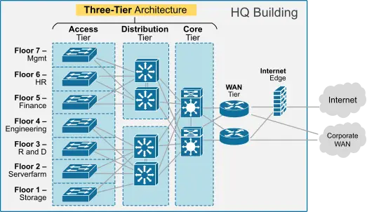
A hierarchical LAN separates network functions into layers. This makes the design easier to scale, manage, and troubleshoot.
Access Layer
The access layer connects endpoints and users directly to the network.
Typical endpoints include:
- Desktop PCs and laptops
- Printers
- IP phones
- Wireless access points
- Cameras and other IoT devices
Common access-layer functions include VLAN membership, port security, Power over Ethernet (PoE), and basic quality-of-service classification.
1 | |
Distribution Layer
The distribution layer aggregates multiple access switches and provides connectivity to network services and the core layer.
Common functions include:
- Inter-VLAN routing
- Route summarization
- Access control and security policies
- Redundant paths and default-gateway services
- Traffic filtering and quality-of-service policies
1 2 3 | |
Core Layer
The core layer provides fast, resilient connectivity between distribution blocks. Its main goals are high availability, low latency, and rapid forwarding.
1 | |
Smaller campus networks may use a collapsed core, in which the distribution and core functions are combined on the same devices.
1.1.3 Redundancy
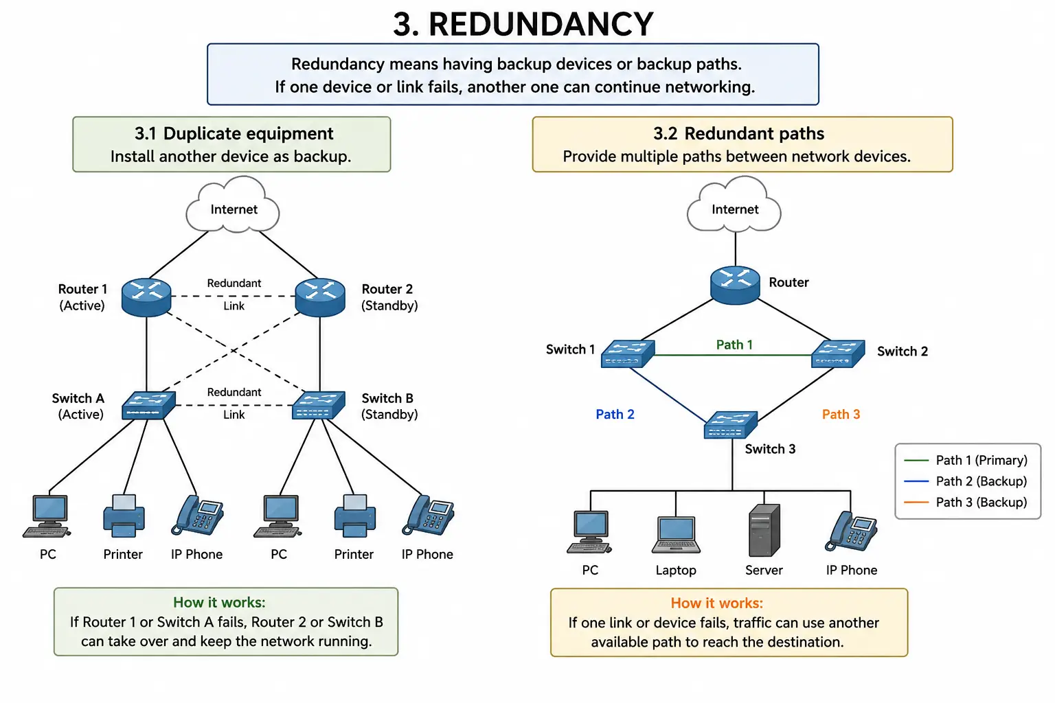
Redundancy means providing backup devices or paths. If one component fails, another component can continue carrying traffic.
Two common methods are:
- Duplicate equipment: Deploy an additional switch, router, power supply, or other device.
- Redundant paths: Provide more than one physical or logical path between network devices.
Redundancy improves availability, but Layer 2 redundant paths must be controlled by technologies such as STP to prevent switching loops.
1.1.4 Failure Domain
A failure domain is the part of a network affected when a device, link, or service fails.
- A large failure domain means one failure can affect many users.
- A small failure domain limits the impact and simplifies troubleshooting.
- Hierarchical designs create predictable boundaries and help contain failures.
1.1.5 Link Aggregation
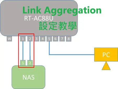
Link aggregation combines multiple physical links into one logical link.
Advantages include:
- Increased aggregate bandwidth
- Link-level redundancy
- Load distribution across member links
- Simpler STP operation because the bundle appears as one logical link
1.1.6 EtherChannel
EtherChannel is Cisco's implementation of link aggregation for Ethernet switch links.
Important points:
- All member interfaces should use compatible speed, duplex, trunk, and VLAN settings.
- STP treats the EtherChannel as one logical interface.
- PAgP is Cisco proprietary; LACP is the IEEE standard protocol.
- A static EtherChannel can be configured without a negotiation protocol.
1.1.7 Wireless NIC and AP
A wireless client needs a wireless network interface card (NIC) and a wireless access point (AP) or wireless router.
1 | |
- The wireless NIC connects the endpoint to the WLAN.
- The AP bridges wireless clients to the wired LAN.
- A home wireless router commonly combines an AP, Ethernet switch, router, DHCP server, and NAT function.
1.1.8 OSPF in Large Networks
Open Shortest Path First (OSPF) is a link-state routing protocol that works well in hierarchical and scalable networks.
Key characteristics include:
- Fast convergence after a topology change
- Neighbor adjacency formation
- Link-state advertisements and a link-state database
- Cost-based path selection
- Hierarchical design using areas
1.2 Selecting Network Devices
Device selection should be based on topology, traffic requirements, availability targets, interface types, management features, and future growth.
1.2.1 Switch Hardware
Switch Categories
Cisco switches are available for different environments:
- Campus LAN
- Data center
- Cloud-managed networks
- Service provider networks
- Industrial networks
- Virtual networking
Port Density
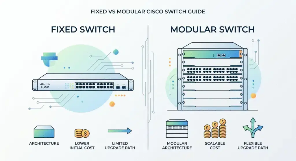
Port density is the number of physical ports available on a switch.
- Fixed-configuration switch: The number and type of ports are built in, such as 24-port or 48-port models.
- Modular switch: Additional line cards or modules can be installed to increase capacity or add interface types.
- Stackable switch: Multiple physical switches can operate and be managed as one logical unit, depending on the platform.
Forwarding Rate
The forwarding rate indicates how many frames or packets a switch can process per second. It is commonly measured in packets per second (pps) or millions of packets per second (Mpps).
Do not confuse it with switching capacity, which is normally measured in Gb/s or Tb/s.
When selecting a switch, verify that its forwarding rate and switching capacity are sufficient for the expected traffic and oversubscription ratio.
Wire Speed
Wire speed or line rate means that an interface or switch can forward traffic at the full advertised rate of its links without becoming the bottleneck.
Examples:
- Fast Ethernet: 100 Mb/s
- Gigabit Ethernet: 1 Gb/s
- 10 Gigabit Ethernet: 10 Gb/s
| IEEE amendment | Standard | Media | Typical maximum distance | Common use |
|---|---|---|---|---|
| 802.3z | 1000BASE-CX | Twinaxial copper | Up to 25 m | Short equipment connections |
| 802.3z | 1000BASE-SX | Multimode fiber | About 220-550 m | Building or data-center links |
| 802.3z | 1000BASE-LX | Multimode or single-mode fiber | Up to 550 m on multimode or about 5 km on single-mode | Campus or building backbone |
| 802.3ab | 1000BASE-T | Cat5e or better twisted pair | Up to 100 m | Desktop and access-switch links |
Power over Ethernet (PoE)
PoE carries data and electrical power over the same Ethernet cable.
Common powered devices include:
- IP phones
- Wireless access points
- IP cameras
- Sensors and other IoT devices
When selecting a PoE switch, check both the PoE standard supported by each port and the switch's total PoE power budget.
Multilayer Switch
A multilayer switch supports both Layer 2 switching and Layer 3 routing. It is commonly deployed at the distribution or core layer.
Layer 2 Switch
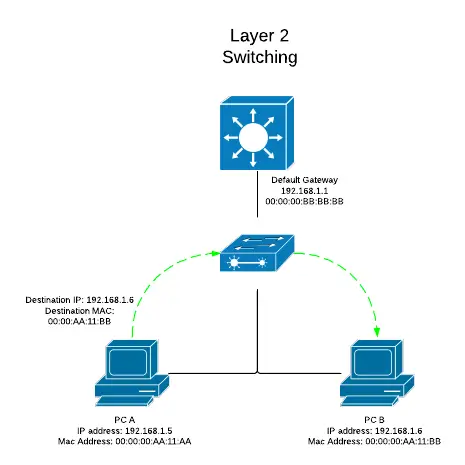
- Forwards Ethernet frames using MAC addresses.
- Maintains a MAC address table.
- Supports VLANs, access ports, and trunk ports.
- Requires a router or multilayer switch for communication between VLANs.
Layer 3 Switch
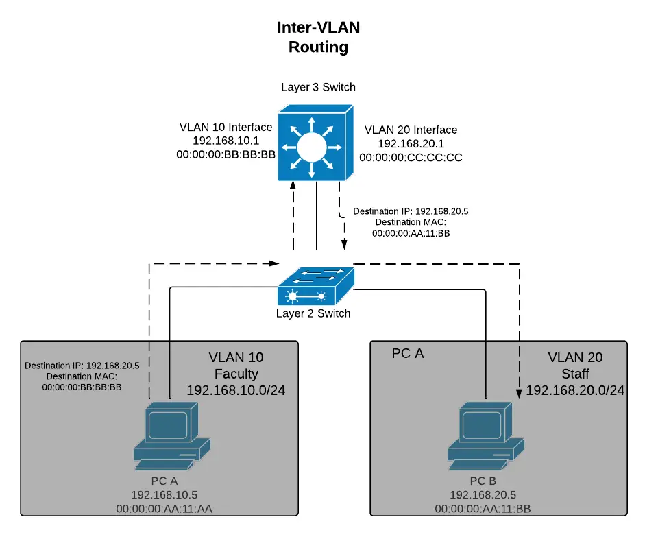
- Performs Layer 2 switching and Layer 3 packet forwarding.
- Maintains both MAC address and IP routing tables.
- Supports switched virtual interfaces (SVIs) and routed ports.
- Can run routing protocols and perform inter-VLAN routing.
1.2.2 Router Hardware
Router Functions
Routers connect different IP networks and choose a path for each packet.
Common functions include:
- Maintaining an IP routing table
- Connecting LANs, WANs, branches, and service providers
- Providing redundant paths
- Network Address Translation (NAT)
- Access control, firewall, VPN, DHCP, and QoS features, depending on the platform and license
- Connecting different media and interface types
Branch Router
A branch router connects a branch office to headquarters, cloud services, the Internet, or other sites. It often combines WAN, VPN, security, and local network services.
Network Edge Router
A network edge router connects an enterprise network to external networks. Typical requirements include high availability, strong security, BGP support, NAT, and multiple WAN links.
Service Provider Router
A service provider router carries large volumes of customer or backbone traffic. It emphasizes high throughput, scalability, modular interfaces, redundancy, and carrier-grade routing features.
Common form factors include desktop, rack-mounted, modular chassis, and blade-based platforms.
1.2.3 Managing Devices
IOS
Cisco IOS (Internetwork Operating System) provides routing, switching, security, management, and automation functions through a command-line interface and other management methods.
Out-of-band Management
Out-of-band management uses a path separate from normal production traffic.
1 | |
Advantages:
- Works when the production network is unavailable.
- Useful for initial configuration and recovery.
- Does not require an IP address on the device.
In-band Management
In-band management uses the production IP network.
1 | |
Common methods include SSH, HTTPS, SNMP, NETCONF, and RESTCONF. SSH is preferred over Telnet because SSH encrypts the management session.
Basic Router and Switch Configuration
Example router interface configuration:
1 2 3 4 5 6 7 8 9 10 11 | |
Example switch access-port configuration:
1 2 3 4 5 6 7 8 9 10 11 12 13 14 | |
Save and Erase Configuration
Save the running configuration:
1 | |
Erase the startup configuration and reload:
1 2 | |
On switches that store VLAN information in vlan.dat, a complete reset may also require:
1 2 | |
These erase commands are destructive. Verify the target device and back up any required configuration before using them.
Router show Commands
1 2 3 4 5 6 7 | |
Switch show Commands
1 2 3 4 5 6 7 8 9 10 | |
Chapter 2: Scaling VLANs
Learning Objectives
- Configure VTP, VLAN ranges, and DTP-based trunking behavior.
- Troubleshoot VLAN and inter-VLAN routing problems.
- Implement inter-VLAN routing with a multilayer switch.
2.1 VTP, Extended VLANs, and DTP
2.1.1 VTP Concepts and Operation
VLAN Trunking Protocol (VTP) is a Cisco proprietary protocol used to distribute and synchronize VLAN information across trunk links within a VTP domain.
VLAN information is stored in the VLAN database, commonly vlan.dat on older Catalyst platforms.
VTP Components
| Component | Purpose |
|---|---|
| VTP domain | A group of interconnected switches that share VLAN information. Domain names must match. |
| VTP advertisements | Messages sent over trunk links to distribute VLAN changes. |
| VTP mode | Determines whether a switch can create, learn, or forward VTP information. |
| VTP password | Optional authentication value that must match within the domain. |
| Configuration revision | Identifies the newest VLAN database update. A higher revision can overwrite an older database. |
VTP Modes
| Mode | Behavior |
|---|---|
| Server | Creates, modifies, and deletes VLANs, and advertises the changes. |
| Client | Learns VLAN information from VTP servers and normally cannot modify the VLAN database locally. |
| Transparent | Maintains VLANs locally and does not synchronize its VLAN database with the domain; it can forward VTP advertisements. |
VTP uses three main advertisement types:
- Summary advertisements
- Advertisement requests
- Subset advertisements
VTP has versions 1, 2, and 3. Verify device support and keep the VTP version, domain name, and password consistent.
Before adding a used switch to a VTP domain, reset or verify its VTP configuration revision. A switch with a higher revision number may overwrite the domain's VLAN database.
2.1.2 VTP Configuration
A basic sequence is:
- Configure the VTP server.
- Configure the VTP domain name, version, and optional password.
- Configure the VTP clients.
- Create VLANs on the VTP server.
- Verify VTP and VLAN information.
Example server configuration:
1 2 3 4 5 6 7 8 9 | |
Example client configuration:
1 2 3 4 5 6 7 8 9 | |
2.1.3 Normal and Extended VLANs
| VLAN range | VLAN IDs | Notes |
|---|---|---|
| Normal range | 1-1005 | VLAN 1 is the default VLAN; VLANs 1002-1005 are legacy defaults on many Catalyst switches. |
| Extended range | 1006-4094 | Used when more VLAN IDs are required. Support depends on platform and VTP version. |
The source material describes Catalyst 2960 behavior in which extended VLANs are configured in VTP transparent mode. VTP version 3 can support additional extended-range behavior on compatible platforms.
Create and name one VLAN:
1 2 3 4 | |
Create multiple VLANs:
1 2 3 | |
Assign an access port to a VLAN:
1 2 3 4 5 | |
Verify the configuration:
1 2 | |
2.1.4 Dynamic Trunking Protocol
Dynamic Trunking Protocol (DTP) is a Cisco proprietary protocol that negotiates whether a switch link becomes a trunk.
Common commands are:
1 2 3 4 5 | |
dynamic autowaits for the neighbor to initiate trunking.dynamic desirableactively attempts to form a trunk.trunkstatically places the interface in trunk mode.accessstatically places the interface in access mode.nonegotiatedisables DTP frames; configure a static access or trunk mode first.
Best practice for a required static trunk:
1 2 3 | |
Disable dynamic trunking on interfaces connected to endpoints or devices that do not support DTP.
2.2 Troubleshoot Multi-VLAN Issues
2.2.1 VLAN and Access-Port Issues
Common causes include:
- The VLAN does not exist on one or more switches.
- An access port is assigned to the wrong VLAN.
- The interface is shut down or the physical link is disconnected.
- A required VLAN is not allowed across a trunk.
- The native VLAN differs at the two ends of a trunk.
Useful commands:
1 2 3 4 | |
To delete a VLAN:
1 2 3 | |
Deleting a VLAN does not automatically move its access ports into another usable VLAN. Reassign affected ports as required.
2.2.2 Inter-VLAN Routing and Interface Issues
For inter-VLAN routing to work:
- The router or Layer 3 switch must have a Layer 3 connection to every VLAN.
- Router-on-a-stick subinterfaces must use the correct
encapsulation dot1q vlan-idcommand. - The switch link to a router-on-a-stick must operate as a trunk.
- Physical interfaces and subinterfaces must be up.
- End hosts must use the correct default gateway.
Common mistakes include connecting the router to the wrong switch port or assigning the wrong VLAN ID to a subinterface.
Useful commands:
1 2 3 4 | |
2.2.3 IP Addressing Issues
Check the following on every VLAN:
- Host IP address
- Subnet mask
- Default gateway
- Router subinterface or SVI address
- Overlapping or mismatched subnets
Each routed interface, subinterface, or SVI must use an address from the subnet of the VLAN to which it is connected.
2.2.4 VTP Issues
Five common VTP problems are:
- Incompatible VTP versions
- Mismatched VTP passwords
- Incorrect VTP domain names
- All switches configured as clients, leaving no server to create VLANs
- An incorrect or unexpectedly high configuration revision number
Start with:
1 2 3 | |
2.2.5 DTP and Trunk Issues
Three common trunking problems are:
- Trunk mode mismatch: For example, one side is a trunk while the other is statically configured as an access port.
- Allowed VLAN mismatch: A required VLAN is missing from the trunk's allowed list.
- Native VLAN mismatch: The two trunk endpoints use different native VLANs.
Recommended verification commands:
1 2 3 | |
2.3 Layer 3 Switching
Modern enterprise networks use multilayer switches for high-speed hardware-based Layer 3 forwarding.
Two common Layer 3 interface types are:
- Switched virtual interface (SVI)
- Routed physical port
2.3.1 Inter-VLAN Routing with SVIs
An SVI is a logical Layer 3 interface associated with a VLAN. Each VLAN that requires routing normally receives an SVI address that becomes the hosts' default gateway.
Example:
1 2 3 4 5 6 7 8 9 10 11 12 13 14 15 16 17 | |
For an SVI to become operational, the VLAN must exist and normally at least one Layer 2 port in that VLAN must be active.
Verify:
1 2 3 | |
2.3.2 Routed Ports
A routed port is a physical switch port that operates like a router interface:
- It is not associated with a VLAN.
- It does not operate as an access or trunk port.
- It is commonly used for point-to-point Layer 3 links between multilayer switches.
- Cisco IOS routed switch ports do not use router-style subinterfaces.
Example:
1 2 3 4 5 6 | |
2.3.3 Troubleshooting Layer 3 Switching
Check these areas in order:
- VLANs: Required VLANs exist on all relevant switches, access ports use the correct VLANs, and trunk links carry those VLANs.
- SVIs: VLAN IDs, IP addresses, subnet masks, and interface states are correct.
- Routing:
ip routingis enabled and connected, static, or dynamically learned routes exist. - Hosts: IP address, subnet mask, VLAN membership, and default gateway are correct.
- Routed ports:
no switchport, IP addressing, and interface state are correct at both ends.
Useful commands:
1 2 3 4 5 6 7 | |
2.4 Chapter Summary
- VTP reduces VLAN administration by synchronizing VLAN information across trunk links in a VTP domain.
- Server, client, and transparent are the three traditional VTP modes.
- Verify the VTP configuration revision before adding a switch to a domain.
- Normal-range VLANs use IDs 1-1005; extended-range VLANs use IDs 1006-4094.
- DTP negotiates trunking on supported Cisco switch interfaces, but static trunk configuration is normally more predictable.
- Multi-VLAN troubleshooting should check VLAN existence, access-port membership, trunk mode, allowed VLANs, native VLANs, and inter-VLAN routing.
- Layer 3 switches perform inter-VLAN routing with SVIs and use routed ports for Layer 3 point-to-point connections.